Separation and preparative technology for chiral drugs: from recognition mechanism to industrial scale-up
We first set out what chirality is and why drug development places separate requirements on it, then give the four engineering routes to a single enantiomer; Part Four develops the recognition mechanism of chiral chromatography, which is the basis for selection; Parts Five and Six cover the technical characteristics and applicable limits of COSMOSIL CHiRAL chiral columns and ChiralONE chiral media respectively; Parts Seven and Eight are directly executable method development and scale-up workflows; Part Nine is a quick reference. Content marked "our inference" indicates that no published statistical source was found.
Summary Ten key points
The following ten points are a condensed version of the whole document, to help judge in advance how relevant it is to the project in hand. The corresponding section is given in brackets after each.
No.How this document is organised and how to read it
The document is organised in the order concept — mechanism — product — method — scale-up. The first two parts explain what chirality is and why drug development places separate requirements on it; Part Three gives the four engineering routes to a single enantiomer and where the chromatographic route sits among them; Part Four develops the recognition mechanism of chiral chromatography, which is the basis for the selection discussed later; Parts Five and Six introduce the technical characteristics and applicable limits of COSMOSIL CHiRAL chiral columns and ChiralONE chiral media respectively; Parts Seven and Eight are directly executable method development and scale-up workflows; Part Nine is a quick reference.
Suggested reading paths: analysts may start at Parts Four and Seven; process development staff at Parts Three and Eight; project management and regulatory staff may read only Parts Two and Nine. Content marked "our inference" indicates that no published statistical source was found and that it serves only as experience-based reference.
A note on product information
Of the product parameters covered here, the COSMOSIL CHiRAL series is taken from Nacalai Tesque published product literature and ChiralONE from the chiral drug separation solution page at microwants.com. No proprietary product information, brand or model of any other manufacturer is involved; comparisons with comparable technical routes are expressed in terms of technical attributes such as "coated / immobilised type" and do not point to any specific brand.
Chirality is a purely geometric concept, but it determines the design logic of every separation method that follows. This part sets out the concept and the criteria first, before moving to drugs and chromatography.
1.1Definition of chirality and the criteria
An object that cannot be superimposed on its mirror image by translation and rotation is said to possess Chiral(chirality). The left and right hand are the usual analogy: the two hands are mirror images with the fingers in the same correspondence, yet no rotation will superimpose them. The same applies at the molecular level, and a pair of mirror-image, non-superimposable molecules is called a pair of Enantiomers(enantiomers)。
The criteria can be given in two directions.The positive criterion is to look for a chiral unit in the molecule, most commonly a carbon atom bonded to four different groups, called a chiral centre or stereocentre.The negative criterion is more reliable: if the molecule possesses an improper symmetry element(Sₙ, including a mirror plane σ = S₁ and a centre of symmetry i = S₂), then the molecule is achiral. In practice, looking for a mirror plane first is the more efficient approach — a molecule containing a mirror plane is not chiral.
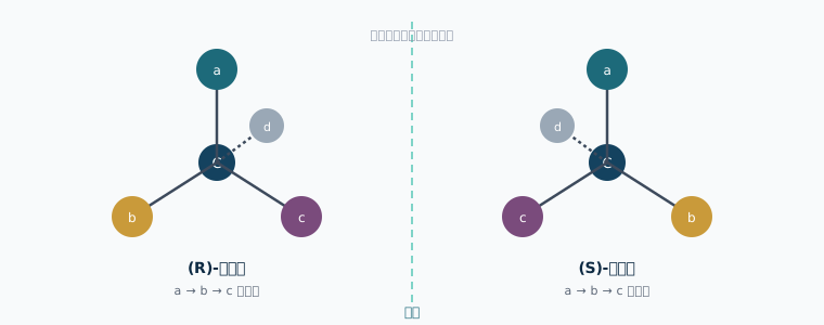
The central carbon carries four different groups a/b/c/d, with the dashed bond pointing behind the plane of the page. The two structures are mirror images and cannot be superimposed by rigid rotation.
1.2Four geometric origins of chirality
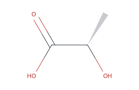
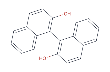
![Structure of 4-carboxy[2.2]paracyclophane · planar chirality (rendered from SMILES by RDKit)](../assets/chiral/struct/paracyclophane.svg)
![Structure of [6]helicene · helical chirality (rendered from SMILES by RDKit)](../assets/chiral/struct/helicene.svg)
Representative structures for the four geometric origins. Central chirality is the commonest; axial, planar and helical chirality do not depend on a chiral carbon, and the criterion remains "not superimposable on its mirror image".
A chiral centre is not the origin of chirality. Drug molecules include several structural types that are chiral without containing a stereocentre, and their chromatographic behaviour differs appreciably.
| Type | Structural features | Typical example | Separation characteristics |
|---|---|---|---|
| Central chirality | A four-coordinate atom bonded to four different groups (C, N⁺, P, S=O and so on) | The stereocentre of most small-molecule APIs | Covered by ordinary chiral stationary phases, with stable configuration |
| Axial chirality | Rotation about a single bond is hindered and the substituents at the two ends are asymmetric — atropisomerism | Biaryl skeletons, 1,1′-binaphthyl structures | Watch the column temperature — a rise may accelerate interconversion and produce a plateau between the peaks |
| Planar chirality | Asymmetry produced by a planar unit combined with an out-of-plane group | Substituted cyclophanes, some ferrocene ligands | Selectivity is relatively sensitive to mobile phase polarity |
| Helical chirality | The whole molecule forms a left- or right-handed helix | Helicenes; the higher-order structure of polysaccharides themselves | Marked groove-matching interaction with polysaccharide stationary phases |
One point relevant to method development
If the interconversion barrier of an atropisomer lies within reach at room temperature, the chromatogram shows a raised plateau between the two peaks (an interconversion plateau). Lowering the column temperature and shortening the retention time will improve the peak shape; if the plateau persists, the compound is not two configurationally stable entities on the timescale of the measurement, and this must be stated in the methodology.
1.3Naming and labelling systems: R/S, D/L, (+)/(−)
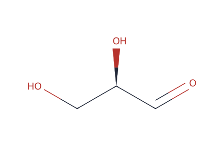
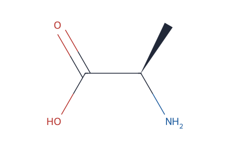
D/L and R/S belong to two separate systems, and (+)/(−) is the measured direction of optical rotation; none can be derived from another.
The three systems are used in parallel, each with its own meaning, and none can be derived from another.
- R/S (the CIP rules)— describes the absolute configuration. The four substituents are ranked by atomic number (a > b > c > d), the lowest priority d is pointed away from the observer, and if a→b→c runs clockwise the centre is R (rectus), anticlockwise S (sinister). This is the main labelling used in regulatory documents and pharmacopoeias today.
- D/L (the Fischer system)— a relative configuration label referenced to glyceraldehyde, used mainly for amino acids and sugars. Natural protein amino acids are mostly L; natural ribose and glucose are mostly D.
- (+)/(−), or d/l— describes the direction of optical rotation, an experimentally measured physical property with no fixed correspondence to R/S. A compound of a given configuration may rotate in different directions at different wavelengths or in different solvents.
A common confusion
Inferences such as "the D configuration must be dextrorotatory" or "the R configuration corresponds to (+)" do not hold. R/S is a geometric description, (+)/(−) is a measurement result and D/L is a relative reference. The three should not be mixed in a report; where drug substance labelling is concerned, use R/S and give the CAS number.
1.4A map of stereoisomeric relationships
Putting the several stereoisomeric relationships on one diagram helps in deciding whether a given impurity should be controlled by a chiral method or an ordinary one.
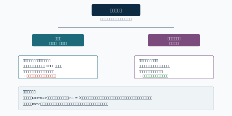
This diagram gives the first branch point in method selection: a chiral method is needed only if the target impurity and the main component are enantiomers.
1.5Where the property differences between enantiomers appear
In an achiral environment a pair of enantiomers have completely identical scalar physical properties: molecular weight, melting point, boiling point, density, refractive index, solubility in an achiral solvent, and retention time on an ordinary C18 column. This is the source of every difficulty in chiral separation — they cannot be separated by "polarity difference" in the usual sense.
Differences appear only once a chiral environment is introduced, and include: interaction with plane-polarised light (optical rotation, circular dichroism); salt or bond formation with a chiral reagent (giving diastereomers, whose properties then differ); and binding to a chiral receptor or chiral stationary phase (forming transient complexes of unequal energy). Chiral chromatography exploits the third of these.
1.6Quantifying chiral purity: e.e., e.r., d.e.
Enantiomeric excess (e.e.) is the most widely used measure today:
e.e. (%) = |R − S| / (R + S) × 100
where R and S are the amounts of the two enantiomers (in chromatography peak areas are usually substituted, on the premise that the response factors of the two enantiomers are the same — for UV detection this premise generally holds, since enantiomers have identical UV absorption)
| Criterion | Definition | Relation to e.e. | Where used |
|---|---|---|---|
| e.e. (enantiomeric excess) | The excess of the major enantiomer over the minor | — | The general expression in regulatory documents and release specifications |
| e.r. (enantiomeric ratio) | The ratio of the two enantiomers, for example 99.5 : 0.5 | e.e. = |difference in e.r.| / sum | Common in the asymmetric synthesis literature; carries the same information as e.e. |
| Enantiomeric impurity content | The minor enantiomer as a percentage of the total | = (100 − e.e.) / 2 | Used when controlling on ICH impurity lines; corresponds directly to a limit |
| d.e. (diastereomeric excess) | The excess of one diastereomer over the other | A parallel concept in a different system | Control of intermediates containing several stereocentres |
| Optical purity | Measured optical rotation / rotation of the pure enantiomer | Ideally equal in value to e.e. | Now seldom used on its own, being sensitive to concentration and impurity interference |
A feel for the numbers
99.0% e.e. corresponds to 0.5% of the minor enantiomer; 99.8% e.e. corresponds to 0.1%. The chiral purity requirement common for drug products falls in the range e.e. ≥ 99.0%–99.8%, which converts to 0.5%–0.1% as an impurity, and this order of magnitude determines the detection limit and resolution required of the analytical method (see section 7.6).
Enantiomers are chemically all but indistinguishable, yet may behave entirely differently in a living body. This part explains where that contrast comes from and gives the corresponding regulatory requirements.
2.1The chiral uniformity of living systems
The basic units of living systems are themselves chiral and occur in nature in a single configuration: proteins are built from L-α-amino acids (glycine excepted), the sugar rings of nucleic acids are D-ribose and D-deoxyribose, and most natural polysaccharides are built from D-glucose. As a result the enzyme active site formed by protein folding, the receptor binding cavity and the transporter channel are all chiral microenvironments。
A drug molecule entering such an environment is like one hand grasping another, fixed hand. A left hand and a right hand inserted into the same glove fit differently — the most direct explanation of pharmacological differences between enantiomers.
2.2The three-point interaction model
The three-point interaction model proposed by Easson and Stedman in 1933 is the basic framework for understanding chiral recognition, and applies equally to biological receptors and to chromatographic stationary phases.
The model requires at least three simultaneous interactions between the chiral recognition site and the molecule being recognised, at least one of which is stereochemically dependent. With only two points of interaction both enantiomers can fit equally well and cannot be distinguished.
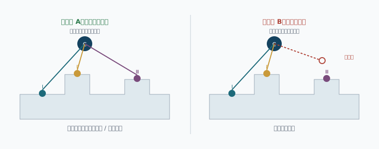
The complexes formed by the two enantiomers with the same chiral surface differ in free energy (ΔΔG), which appears chromatographically as a difference in retention factor k, that is the selectivity factor α = k₂ / k₁.
From ΔΔG to α
The selectivity factor α and the free energy difference between the two enantiomer–stationary phase complexes satisfy ΔΔG = −RT · ln α. At 298 K, α = 1.10 corresponds to an energy difference of only about 0.24 kJ/mol, and α = 1.50 to about 1.0 kJ/mol. The energy differences on which chiral separation depends are therefore very small, which explains why small changes in mobile phase composition or column temperature can change the separation markedly.
2.3Four cases of enantiomer pharmacology
Grouping the pharmacological relationship between enantiomers into four classes maps directly onto development decisions.
| Situation | Characteristics | Representative compound classes | Development implication |
|---|---|---|---|
| Activity concentrated in one enantiomer | One is the eutomer, the other markedly less active | Most receptor agonist/antagonist drugs, such as some quinolones and some proton pump inhibitors | The benefit of developing a single enantiomer is clear, and e.e. control must be established |
| The two enantiomers have similar activity | The target is insensitive to configuration | Some antihistamines, some local anaesthetics | Developing the racemate is acceptable, but whether the PK of the two is the same still has to be addressed |
| One enantiomer produces a different pharmacological action | The two act on different targets, with different effects but both of clinical significance | Cases such as dextromethorphan / levomethorphan, with the same skeleton but divergent action | They must be evaluated separately and treated as different drugs |
| One enantiomer carries the main toxicity or adverse effects | The distomer is associated with toxicity or adverse events | Historically most discussed in relation to thalidomide | The case for developing a single enantiomer is strong, and the other enantiomer is controlled strictly as an impurity |
2.4Stereoselective ADME and chiral inversion in vivo
Differences between enantiomers are not confined to target binding. Absorption, distribution, metabolism and excretion are all mediated by chiral proteins, so the pharmacokinetic parameters of the two enantiomers may differ:
- Metabolism— CYP isoforms are selective for configuration, so the clearance and metabolite profile of the two enantiomers may differ; the S and R forms of an anticoagulant being metabolised by different CYP pathways is the classic example.
- Plasma protein binding— albumin and α₁-acid glycoprotein are themselves chiral recognition entities, so the free fraction can differ with configuration.
- Transport— efflux transporters such as P-gp have configurational preferences.
- Chiral inversion in vivo— the R form of some 2-arylpropionic acids can be converted enzymatically and unidirectionally to the S form in vivo. Even when such a compound is given as a single enantiomer, exposure in vivo is to a mixture of both, which must be addressed in clinical pharmacology.
The direct effect on analytical work
For a product subject to chiral inversion in vivo, bioanalysis must use a chiral method to quantify the two enantiomers separately; an ordinary achiral LC-MS/MS method combines them, biasing the interpretation of the PK parameters.
2.5The thalidomide case and what it means technically
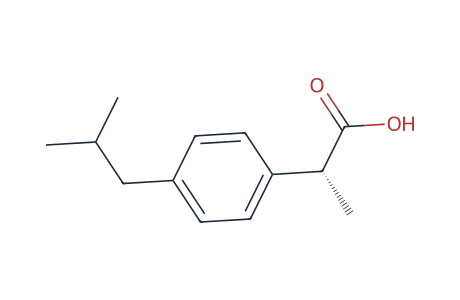
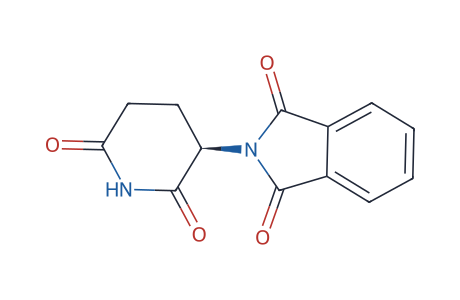
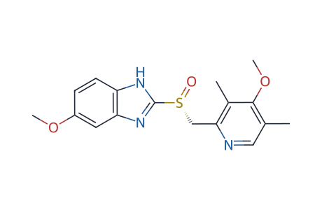
Three typical cases: unidirectional conversion in vivo; enantiomers that behave differently and can interconvert; and a racemate relaunched as a single enantiomer.
Thalidomide was marketed in the late 1950s as a sedative and antiemetic, and was later withdrawn after being linked to limb malformations in newborns. Subsequent research showed that its two enantiomers behave differently biologically, with the (S) configuration associated with teratogenicity.
It must be said at the same time that the stereocentre of thalidomide undergoes rapid racemisation at physiological pH, so that even when a single enantiomer is administered a mixture of both forms rapidly in vivo. The technical conclusion from the case is therefore not "giving a single enantiomer avoids the risk" but that enantiomers must be identified and evaluated separately— including their configurational stability. This understanding drove the establishment of the regulatory framework that followed.
2.6The regulatory framework and control requirements for chiral impurities
| Document | Issuing body | Key requirements |
|---|---|---|
| Policy Statement for the Development of New Stereoisomeric Drugs(1992) | FDA | Requires that the pharmacological and toxicological characteristics of each stereoisomer be described for a new drug containing a stereocentre; where a racemate is developed, the basis for choosing that form must be provided; analytical methods capable of measuring each isomer must be available |
| ICH Q6A | ICH | Sets out the principles for establishing specifications for drug substance and drug product; for chiral products the specification must include identification (by optical rotation or chiral chromatography) and a limit for the enantiomeric impurity |
| ICH Q3A(R2) / Q3B(R2) | ICH | The framework of reporting, identification and qualification thresholds for impurities; enantiomeric impurities are generally managed within this framework, but because their toxicological properties may differ the limit often has to be justified separately |
| ICH Q2(R2) | ICH | Requirements for analytical method validation: specificity, linearity, accuracy, precision, LOD and LOQ, robustness; for a chiral method, specificity and LOQ are the focus |
| The relevant general chapters of Volume IV of the Chinese Pharmacopoeia and the NMPA technical guidance on chiral drug research | NMPA | Requires description of the origin of chirality, configurational stability, and the analytical method and basis of the limit for the enantiomeric impurity; a generic single-enantiomer product must be comparable to the reference product in chiral purity |
The general approach to setting a limit
The limit for an enantiomeric impurity is not automatically the 0.15%/0.10% identification threshold of ICH Q3A. Where toxicology data already support the safety of the minor enantiomer the limit may be relaxed with justification; where there are no data, control is usually at a stricter level. In practice drug substance requirements commonly range from e.e. ≥ 99.0% (enantiomeric impurity ≤ 0.5%) to ≥ 99.8% (≤ 0.1%) (our inference; the registration dossier for each product governs).
2.7The product logic of the chiral switch
A marketed racemic drug may be redeveloped as a new product if the single enantiomer can be shown to offer an advantage in efficacy or safety; this strategy is called a chiral switch. It has three technical prerequisites: the two enantiomers do behave differently pharmacologically; the single enantiomer can be obtained reliably at industrial scale; and the single enantiomer does not racemise rapidly in vivo.
For separation technology, a chiral switch means demand expands from "analytical-scale e.e. determination" to "kilogram- to tonne-scale preparation of a single enantiomer" — which is the subject of Part Eight.
Chromatographic resolution is not the only route, but it has a defined place in terms of response speed and range of application at the development stage. This part compares the four routes on the same axes.
3.1The chiral pool route
Starting from a single-configuration compound already available in nature, the target molecule is built by reactions that do not destroy the stereocentre. Common chiral pool starting materials include L-amino acids, D-sugars, terpenes, hydroxy acids (L-tartaric and L-malic acid, for example) and alkaloids.
The advantages of this route are high starting chiral purity, controllable cost and no resolution step; the constraints are that the skeleton of the target molecule must match structurally what is available as a chiral starting material, and that every step of the synthesis must avoid racemising the stereocentre.
3.2Asymmetric synthesis and asymmetric catalysis
The configuration of the new stereocentre is controlled directly in the bond-forming step. Three classes can be distinguished by where the chiral information comes from:
- A chiral auxiliary— a chiral group is attached temporarily to the substrate and removed after the reaction. Stereocontrol is reliable, but two extra steps of attachment and removal are needed and atom economy is lower.
- A chiral reagent— a chiral reducing or oxidising agent used stoichiometrically.
- Asymmetric catalysis— a chiral catalyst transfers chiral information at substoichiometric loading. Metal complex catalysis (asymmetric hydrogenation, epoxidation, dihydroxylation), small-molecule organocatalysis and biocatalysis (enzymes, engineered enzymes) all belong here. The Nobel Prizes in Chemistry of 2001 and 2021 were awarded to asymmetric catalytic hydrogenation/oxidation and to asymmetric organocatalysis respectively, reflecting the standing of this direction in industrial synthesis.
In a mature process, asymmetric catalysis is optimal in atom economy and throughput, but catalyst screening and process development take longer and depend strongly on substrate structure.
3.3Crystallisation resolution and kinetic resolution
| Method | Principle | Theoretical maximum yield | Principal limitations |
|---|---|---|---|
| Classical diastereomeric salt crystallisation | Salt formation with a chiral acid or base gives a pair of diastereomeric salts, separated by fractional crystallisation on their solubility difference | 50% (if the other half is not recovered) | The substrate must contain a group capable of salt formation; resolving agent screening is empirical; mother liquor treatment and recycling make the process complex |
| Preferential crystallisation | Alternate seeding with crystals of each enantiomer in a conglomerate system | Close to 100% (cyclic operation) | Applies only to systems forming a racemic conglomerate, which are a small proportion |
| Kinetic resolution (KR) | A chiral catalyst or enzyme reacts with the two enantiomers at different rates | 50% | A trade-off between e.e. and conversion is needed; the e.e. of the remaining enantiomer rises as conversion increases |
| Dynamic kinetic resolution (DKR) | Kinetic resolution coupled with in situ racemisation of the substrate | Up to 100% in theory | The substrate must racemise rapidly under the reaction conditions, and the condition window is narrow |
| Deracemisation | An oxidation–asymmetric reduction cycle or similar converts the whole racemate into one configuration | Up to 100% in theory | System design is complex and industrial cases are relatively limited |
3.4Chromatographic resolution
The racemate is separated directly on a chiral stationary phase (CSP), or converted first by chiral derivatization into diastereomers and separated on an ordinary column. Its characteristics are:
- The route is independent of the synthesis— the existing synthetic route is unchanged, and the step can be inserted at any intermediate or at the final product.
- Short development time— for most compounds the column and mobile phase can be screened within days to give a usable method.
- Both enantiomers are obtained— the minor enantiomer can be kept as an impurity reference standard, or racemised and recycled.
- Wide range of application— there is no requirement for the substrate to contain a salt-forming group or a reactive functional group.
The cost lies in solvent consumption and stationary phase cost at the preparative stage. Part Eight gives a quantitative treatment of both.
3.5Matching the route to the development stage
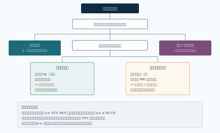
Development stage and quantity required are the main branching variables; whichever route is chosen, a chiral analytical method is prerequisite work.
| Dimension | Chiral pool | Asymmetric catalysis | Crystallisation / kinetic resolution | Chiral chromatography |
|---|---|---|---|---|
| Development time | Medium (depends on route design) | Long (catalyst screening) | Medium (resolving agent screening) | Short (days to weeks) |
| Range of substrates | Narrow, limited by skeleton | Medium, depends on substrate type | Medium, requires specific functional groups | Wide, essentially unrestricted by functional group |
| Theoretical yield | Close to quantitative | Close to quantitative | 50% (DKR can improve this) | Close to quantitative (both enantiomers can be collected) |
| Typical e.e. attainable | Determined by the starting material | 90%–99% | 95%–99.5% | ≥ 99.5% (can be raised by recycling) |
| Upper limit of scale | Tonne | Tonne | Tonne | Hundreds of kilograms to tonnes (continuous chromatography) |
| Principal cost item | Chiral starting material | Catalyst and ligand | Resolving agent and mother liquor treatment | Stationary phase and solvent |
| Suitability in early development | Medium | Low | Medium | High |
Chiral column selection, mobile phase design and temperature setting can all be derived from the recognition mechanism. This part is the basis for the two product chapters that follow.
4.1The molecular basis of chiral recognition
The types of interaction between a chiral stationary phase and the molecule being separated are no different from those in ordinary chromatography; the difference is that they take place in a chiral environment of fixed spatial orientation and are therefore sensitive to configuration. The common types are:
| Type of interaction | Origin in a polysaccharide stationary phase | Affected by the mobile phase | Means of control |
|---|---|---|---|
| Hydrogen bonding | The N–H (donor) and C=O (acceptor) of the carbamate group | Alcohol modifiers compete strongly | Adjust the type and proportion of alcohol |
| Dipole–dipole | The polar groups of the carbamate | Varies with mobile phase polarity | Choice of modifier polarity |
| π–π interaction | Aromatic rings on the selector; substituent electronic effects change its strength | Affected by solvent aromaticity | Change the selector (aromatic substitution pattern) |
| Steric hindrance and inclusion | The chiral grooves formed by the higher-order polysaccharide helix | Relatively insensitive; the main source of selectivity | Change the selector backbone (amylose / cellulose) |
| Hydrophobic interaction | Hydrophobic contact between the selector backbone and the solute under reversed phase conditions | Varies with the proportion of the aqueous phase | Adjust the proportion of organic phase |
| Ionic interaction | Used in ion exchange CSPs; in polysaccharide types it usually has to be suppressed with an additive | Controlled by pH and ionic strength | Add an acidic or basic additive |
The net result of chiral recognition is a free energy difference ΔΔG between the transient complexes the two enantiomers form with the stationary phase. This difference is usually of the order of 0.2–2 kJ/mol, corresponding to α = 1.1–2.2. Robustness studies on a chiral method are therefore more important than on an ordinary one.
4.2Seven classes of chiral stationary phase
| Category | Selector | Principal recognition mechanism | Applicability and limitations |
|---|---|---|---|
| Polysaccharide derivative type | Tri-substituted phenylcarbamate / benzoate of amylose or cellulose | Helical groove inclusion + hydrogen bonding + π–π | The widest range of application, covering most neutral, acidic and basic small molecules; currently the most used in drug development and preparative work |
| Brush type (Pirkle type) | A small-molecule chiral selector, such as a π-acid/π-base aromatic amide | Three-point interaction, with a clear mechanism | Suits specific structures containing aromatic rings, with higher loading; narrower coverage than the polysaccharide types |
| Cyclodextrin type | α/β/γ-cyclodextrin and its derivatives | Inclusion in a hydrophobic cavity | Applicable under reversed phase conditions, suiting compounds whose size matches the cavity |
| Macrocyclic glycopeptide type | Macrocyclic antibiotics such as vancomycin and teicoplanin | Multiple interaction sites | Works well for amino acids and amphoteric compounds |
| Protein type | α₁-acid glycoprotein, human serum albumin, ovomucoid | The protein binding cavity | Aqueous reversed phase conditions only; low loading, used mainly for analysis and plasma protein binding studies |
| Ligand exchange type | A chiral amino acid–metal ion complex | Differences in the stability of the ternary complex | Suits amino acids, hydroxy acids and other compounds that coordinate to metals |
| Crown ether type | Chiral crown ethers | Host–guest recognition of the primary ammonium proton | Suits free primary amine compounds, under fairly specific conditions |
The first principle of selection
With no prior structural information, starting the screen with a polysaccharide derivative stationary phase gives the higher hit rate. The hit rate data for the three selectors given in section 5.5 can serve as the basis.
The molecular structures on this page are rendered from SMILES by RDKit, with molecular formula and ring count verified by assertion one by one; the structures show the skeleton and key functional groups, and the original source governs the stereochemistry.
4.3The structural origin of polysaccharide stationary phases
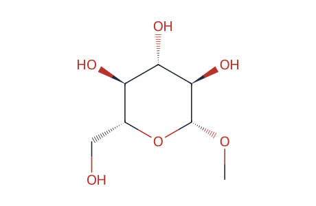
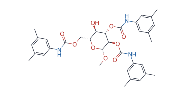
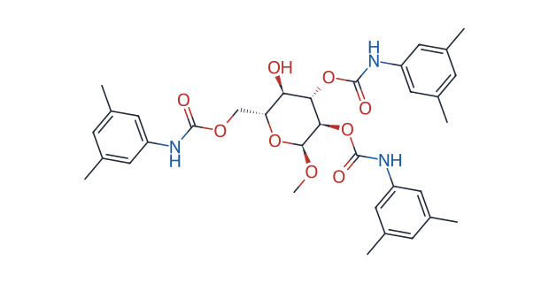
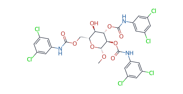
The repeating unit of each selector is shown as the methyl glycoside: in the real material the 4-hydroxyl forms the glycosidic bond of the polymer chain, and the free 4-OH in the figure marks where the chain is cut. The three differ only in linkage (β-1,4 / α-1,4) and ring substituent (methyl / chloro), and that is where their complementary selectivity comes from.
Cellulose and amylose are themselves homopolymers of D-glucose, differing in the configuration of the glycosidic bond: cellulose is β-1,4 linked with a relatively extended, ribbon-like chain, while amylose is α-1,4 linked and the chain tends to coil into a helix. Derivatising the three hydroxyls on the sugar unit as phenylcarbamates produces two effects:
- a large number of uniformly oriented N–H / C=O hydrogen bonding sites and aromatic rings;
- the derivatised polysaccharide chains form a regular higher-order structure during immobilisation, and between and within chains they create chiral grooves。
Once the molecule being separated enters the groove, the spatial relationship of its substituents to the hydrogen bonding sites and aromatic rings on the groove wall depends on configuration — this is the main source of chiral recognition on polysaccharide stationary phases. It is also why the position and electronic character of the ring substituents (methyl, chloro, mixed substitution) change the shape and electron density of the groove and give different selectivity profiles.
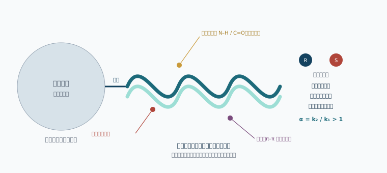
From silica substrate through the bonded layer and polysaccharide helix to the chiral groove, selectivity arises mainly in the outermost layer.
4.4Differences between coated and immobilised types
There are two ways of loading a polysaccharide derivative onto silica, and this difference determines the range of usable solvents — one of the technical attributes with the greatest influence on chiral column selection.
- Coated type— the selector is attached to the silica surface by physical adsorption, with no chemical bond. Preparation is relatively simple and the natural higher-order structure of the selector is better preserved; but the selector can be dissolved by strong solvents and washed off the support.
- Immobilised type (that is, bonded)— a chemical bond is formed between the selector and the silica. The selector cannot be washed off by solvent, and the range of usable solvents widens markedly.

The COSMOSIL CHiRAL series uses an immobilised (chemically bonded) selector; see the measured data in section 5.2.
Three practical gains from immobilisation
- A wider selectivity space— more usable solvents means more screening combinations along the mobile phase dimension. For a difficult separation, changing the solvent often works faster than changing the column.
- Sample solubility problems eased— the preparative stage is often limited by sample solubility in the mobile phase. Dissolving in dichloromethane, chloroform or THF can raise the amount injected per run markedly.
- Wider conditions for column cleaning and regeneration— flushing with a strong solvent will not strip the selector, so there are more ways to recover a fouled column.
4.5Four elution modes
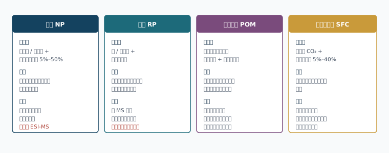
The same chiral column does not give the same selectivity in different modes, and screening one round in each mode during method development is standard practice.
4.6How solvent affects selectivity
In ordinary reversed phase chromatography, changing the proportion of organic phase mainly affects retention (k), with limited change in selectivity (α). Chiral chromatography is different:the solvent takes part in the chiral recognition process itself. Alcohol modifiers compete for the hydrogen bonding sites on the carbamate, and different alcohols (methanol, ethanol, isopropanol) differ in steric bulk and hydrogen bonding ability, changing the solvation state inside the groove and hence α — sometimes even reversing the elution order of the two enantiomers.
In chiral method development, therefore,changing the type of modifier takes priority over adjusting its proportion. It is not unusual for a separation with α = 1.05 in hexane/isopropanol to rise to α = 1.3 in hexane/ethanol.
4.7Temperature effects and reversal of elution order
The relationship between retention and temperature is described by the van 't Hoff equation:
ln k = −ΔH° / (RT) + ΔS° / R + ln φ
Taking the difference for a pair of enantiomers gives ln α = −ΔΔH° / (RT) + ΔΔS° / R. This means:
- When the separation is enthalpy dominated(ΔΔH° is the main contribution), lowering the column temperature raises α. This is the common situation on most polysaccharide stationary phases, which is why chiral methods often run at 15–25 °C.
- When ΔΔH° and ΔΔS° have the same sign and offset one another, there is an isoelution temperature T_iso = ΔΔH° / ΔΔS°. At that temperature α = 1 and the two peaks coincide; on crossing it,the elution order reverses。
What this means methodologically
If column temperature control is unstable and the working temperature is close to the isoelution temperature, e.e. results will fluctuate inexplicably and the assignment of major and minor peaks may even invert. A robustness study on a chiral method should treat column temperature ±5 °C as a mandatory variable, and the method should specify a column temperature rather than "ambient".
4.8Reading the resolution equation in chiral separation
The basic relationship for resolution is:
Rs = (√N / 4) · [(α − 1) / α] · [k / (1 + k)]
The three factors differ greatly in how far they can be manipulated in a chiral separation:
| Factor | Means of control | Scale of improvement | Notes |
|---|---|---|---|
| α (selectivity) | Change the selector, change the type of modifier, adjust column temperature | Large | Address this first. Raising α from 1.05 to 1.20 raises the selectivity term of Rs by about 3.5 times |
| N (efficiency) | Reduce particle size (5 µm → 3 µm), increase column length, lower flow rate | Medium | Rs Proportional to √N, so doubling column length gives only about 1.41 times; reducing particle size raises N without increasing run time |
| k (retention) | Reduce the proportion of modifier | Small (once k > 5) | Raising k from 1 to 5 is effective; beyond k > 10 the gain is small while run time lengthens markedly |
The conclusion is clear: the main effort in chiral method development should go into raising α — that is, changing column and changing solvent — rather than lengthening the column or lowering the flow rate.
The parameters in this part are taken from Nacalai Tesque published product literature (the COSMOSIL CHiRAL Series product page and product handbook). Microwants is the exclusive agent for this series in mainland China.
5.1Range composition and technical parameters
The COSMOSIL CHiRAL series uses silica as the substrate with chemically bonded (immobilised)polysaccharide derivatives as the chiral selector, in three selectors and two particle sizes.
| Item | CHiRAL 3A / 5A | CHiRAL 3B / 5B | CHiRAL 3C / 5C |
|---|---|---|---|
| Chiral selector | Amylose tris(3,5-dimethylphenylcarbamate) Amylose tris(3,5-dimethylphenyl carbamate) | Cellulose tris(3,5-dimethylphenylcarbamate) Cellulose tris(3,5-dimethylphenyl carbamate) | Cellulose tris(3,5-dichlorophenylcarbamate) Cellulose tris(3,5-dichlorophenyl carbamate) |
| How the selector is fixed | Immobilised (chemically bonded) | ||
| Base matrix | Silica | ||
| Particle size | 3 µm (analytical), 5 µm (analytical / preparative) | ||
| Usable pH | 2 – 9 | ||
| USP code | L99 | — | L119 |
| Backbone difference | α-1,4 glycosidic bonds, chain tending to a helix | β-1,4 glycosidic bonds, chain extended in a ribbon | β-1,4 backbone with electron-withdrawing chloro substitution, lowering the electron density of the π system |
The design intent behind the three selectors
A and B have the same substituent (3,5-dimethylphenyl) and differ only in the polysaccharide backbone — giving orthogonality along the "backbone dimension". B and C have the same backbone (cellulose) and differ in the ring substituent, electron-donating methyl replaced by electron-withdrawing chloro — giving orthogonality along the "electronic effect dimension". Together they form a screening set covering two dimensions, rather than three columns with duplicate performance.
5.2Solvent tolerance of an immobilised selector
A comparison published by the manufacturer: using trans-stilbene oxide as the probe on a 2.6 mm I.D. × 250 mm column with hexane/isopropanol = 90/10 at 1.0 mL/min, 30 °C and UV 270 nm, tetrahydrofuran (THF) was injected repeatedly.
- A coated selector: THF strips the selector from the stationary phase and the plate count falls below one fifth of its original value.
- An immobilised selector (COSMOSIL CHiRAL): withstands repeated injection of THF.
This difference sets the working boundary of the column directly: a sample solution containing THF or dichloromethane can be injected as it is, with no solvent exchange first. In impurity preparation and direct analysis of reaction mixtures, this saves a sample preparation step.
5.3The usable solvent range and the selectivity space
| mobile phase | Immobilised · normal phase | Immobilised · reversed phase | Coated · normal phase |
|---|---|---|---|
| Hexane | Usable * | — | Usable * |
| n-Heptane | Usable | — | Usable |
| Methanol | Usable * | Usable | Usable * |
| Ethanol | Usable | Usable | Usable |
| Isopropanol | Usable | Usable | Usable |
| Acetonitrile | Usable * | Usable | Usable * |
| Tetrahydrofuran (THF) | Usable | Usable | Not usable |
| Methyl tert-butyl ether (MTBE) | Usable | — | Not usable |
| Toluene | Usable | — | Not usable |
| Chloroform | Usable | — | Not usable |
| Dichloromethane | Usable | — | Not usable |
| Ethyl acetate | Usable | — | Not usable |
| Water / aqueous buffer | — | Usable | — |
* Methanol and acetonitrile are immiscible with hexane and should not be combined into the same mobile phase.
Order of eluting strength (normal phase): alcohols, THF ≫ chloroform > MTBE ≫ alkanes.
An example of selectivity changing with solvent
The published literature illustrates this with the separation of 1-acenaphthenol on CHiRAL 3B (4.6 mm I.D. × 250 mm), showing how the result differs when the mobile phase solvent is changed. This is consistent with the mechanism in section 4.6: the solvent takes part in chiral recognition, and changing the type of solvent is one of the main ways of raising α. An immobilised selector expands the number of solvents that can be tried from about 6 to more than 12, widening the combinatorial space of method development accordingly.
5.4Efficiency and backpressure of the 3 µm particle size
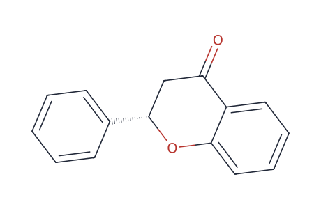
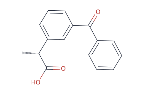
COSMOSIL CHiRAL offers 3 µm analytical columns. Relative to a conventional 5 µm, the gains and costs are as follows:
- Efficiency— peak width is reduced; the published literature shows the improvement in peak shape of 3 µm over 5 µm with comparison chromatograms of flavanone and ketoprofen on a 4.6 mm I.D. × 250 mm column. On the Rs ∝ √N relationship, reducing particle size from 5 µm to 3 µm raises N by about 1.67 times in theory and Rs by about 1.29 times — and in a borderline separation where α is close to 1.05–1.10, that increment often decides whether the method is usable.
- Backpressure— on a 4.6 mm I.D. × 250 mm column at 1.0 mL/min and 30 °C in a hexane/isopropanol system: backpressure is 5.3 MPa at 5% (v/v) isopropanol, and does not exceed 12 MPa when isopropanol is raised to 50% (v/v). This range places no pressure constraint on an ordinary HPLC system, so the mobile phase composition can be adjusted over a wide range.
A gain that is easily overlooked
A pure alkane mobile phase has low viscosity and very low backpressure, and some HPLC pumps deliver less stably at very low backpressure, causing retention time drift. The moderate rise in backpressure from a 3 µm column actually helps the reproducibility of such systems.
5.5Screening hit rates of the three selectors
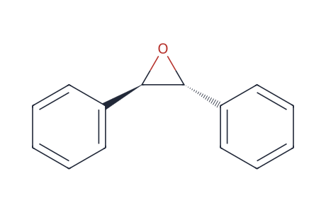
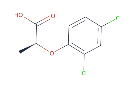
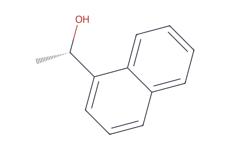
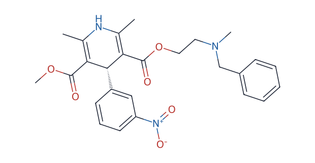
The probes used in the hit rate trial and the four-sample comparison, covering neutral, acidic and basic classes.
The screening trial published by Nacalai Tesque: 28 racemic samples, with a resolution Rs ≥ 1.5 taken as "complete separation (a hit)".
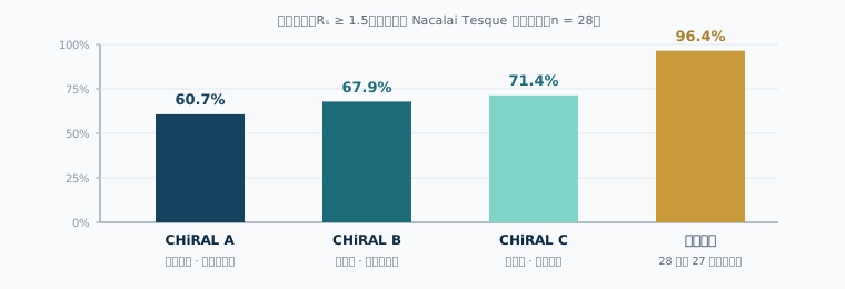
The best single column reaches 71.4%; screening on all three covers 27 of the 28 samples.
This has two practical implications. First,a single column is not enough— even the selector with the highest hit rate leaves about 28.6% of samples short of Rs ≥ 1.5, so chiral method development should start from multi-column screening rather than "picking one good column". Second,the failures of the three selectors do not overlap— precisely because of the orthogonality along the backbone and substituent dimensions, combined coverage is markedly higher than that of any single column.
| Sample | Mobile phase | CHiRAL A | CHiRAL B | CHiRAL C |
|---|---|---|---|---|
| trans-Stilbene oxide | Hexane / isopropanol = 90 / 10 | Complete separation (best) | Complete separation | Complete separation |
| 2-(2,4-Dichlorophenoxy)propionic acid | Hexane / isopropanol / TFA = 95 / 5 / 0.1 | Complete separation (best) | Partial separation | Complete separation |
| 1-(1-Naphthyl)ethanol | Hexane / isopropanol = 90 / 10 | Partial separation | Complete separation (best) | Complete separation |
| Nicardipine | Hexane / isopropanol / diethylamine = 90 / 10 / 0.1 | Partial separation | Partial separation | Complete separation (best) |
5.6SFC compatibility
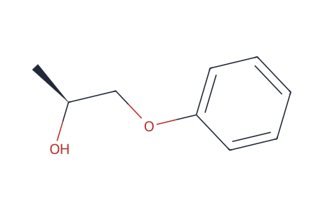
COSMOSIL CHiRAL columns can be used in supercritical fluid chromatography. The published literature gives two sets of parallel HPLC and SFC conditions:
| Sample | Column | HPLC conditions | SFC conditions |
|---|---|---|---|
| trans-Stilbene oxide 2.0 mg/mL | CHiRAL 3A | Hexane / isopropanol = 90/10; 1.0 mL/min; 30 °C; UV 254 nm; 1.0 µL injected | A: CO₂, B: isopropanol, 10% B; 3.0 mL/min; backpressure 10 MPa; 40 °C; UV 254 nm; 2.0 µL injected |
| 1-Phenoxy-2-propanol 1.0 mg/mL | CHiRAL 3C | Hexane / isopropanol = 90/10; 1.0 mL/min; 30 °C; UV 270 nm; 1.5 µL injected | A: CO₂, B: isopropanol, 10% B; 3.0 mL/min; backpressure 10 MPa; 40 °C; UV 270 nm; 3.0 µL injected |
Flow rate under SFC is three times higher while, according to the published literature, the separation performance is comparable to HPLC. For preparative work this means higher throughput per unit time, and since the bulk of the mobile phase is CO₂ the solvent evaporation load in work-up is far lower than for normal phase HPLC.
5.7Conditions for neutral / acidic / basic compounds
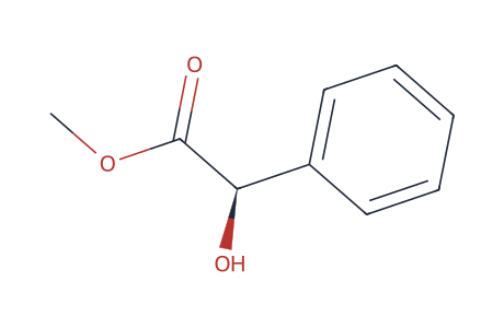
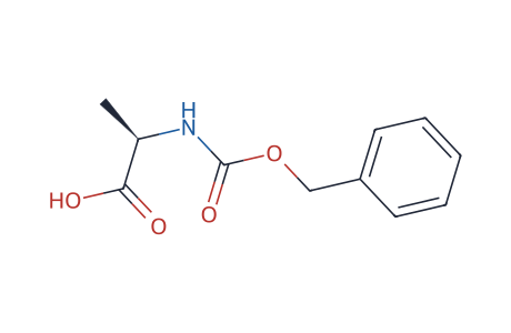
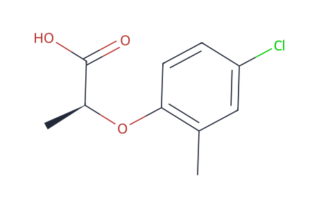
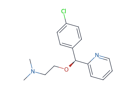
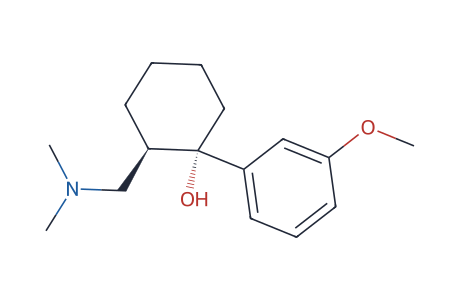
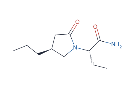
Arranged in the order neutral, acidic, basic. Adding about 0.1% acid for an acidic sample and about 0.1% base for a basic one is standard practice in normal phase chiral separation.
The published application conditions can be summarised in one practical rule:add about 0.1% acid for an acidic compound and about 0.1% base for a basic one, to suppress ionic interaction between the solute and residual silanols on the silica and improve tailing and detection.
| Type | Sample | Column | Mobile phase | Detection |
|---|---|---|---|---|
| Neutral | Methyl DL-mandelate 1.0 mg/mL | CHiRAL 3B | Hexane / isopropanol = 90 / 10 | UV 220 nm |
| 1,1′-Bi-2-naphthol 0.5 mg/mL | CHiRAL 3C | Hexane / isopropanol = 90 / 10 | UV 335 nm | |
| Acidic | N-benzyloxycarbonyl-DL-alanine 0.5 mg/mL | CHiRAL 3B | Hexane / isopropanol / TFA = 90 / 10 / 0.1 | UV 210 nm |
| Mecoprop 0.5 mg/mL | CHiRAL 3A | Hexane / isopropanol / TFA = 95 / 5 / 0.1 | UV 230 nm | |
| Basic | Carbinoxamine 1.0 mg/mL | CHiRAL 3A | Hexane / isopropanol / diethylamine = 90 / 10 / 0.1 | UV 225 nm |
| Tramadol 1.0 mg/mL | CHiRAL 3C | Hexane / isopropanol / diethylamine = 95 / 5 / 0.1 | UV 225 nm |
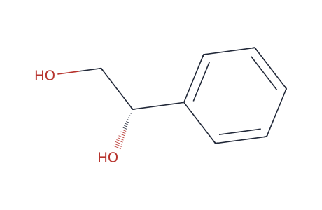
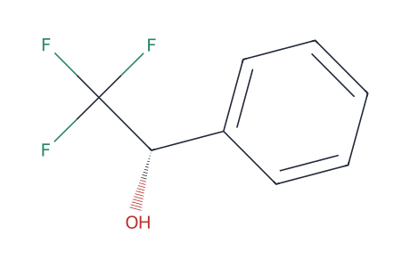
The published literature also includes application data from users, covering indole amides, oxadiazolopyrazines, β-hydroxy ketones, branched carboxylic acids, phenyl glycols, trifluoromethyl benzyl alcohols, exo/endo adducts of bicyclic enones, tetrahydropyrrolocarbazolones, 3-butyl-7-hydroxyphthalide and brivaracetam, ranging from simple alcohols and acids to complex skeletons with several stereocentres.
5.8Available formats and selection advice
| Particle size | Column ID × length | Role | Selectors available |
|---|---|---|---|
| 3 µm | 4.6 mm I.D. × 150 mm | Rapid screening and routine analysis | 3A / 3B / 3C |
| 4.6 mm I.D. × 250 mm | Analysis and method validation | 3A / 3B / 3C | |
| 5 µm | 4.6 mm I.D. × 250 mm | Analysis, and the scale-up reference column for preparative work | 5A / 5B / 5C |
| 10.0 mm I.D. × 250 mm | Semi-preparative, milligram to hundreds of milligrams | 5A / 5B / 5C | |
| 20.0 mm I.D. × 250 mm | Preparative, hundreds of milligrams to grams | 5A / 5B / 5C |
Selection advice
- Starting point for method development: the three columns A / B / C in 3 µm, 4.6 × 150 mm, with two normal phase modifiers (ethanol, isopropanol), giving six initial screening conditions.
- Method validation and release: move to 3 µm, 4.6 × 250 mm for more Rs margin, to meet the requirements of the robustness study.
- Preparative scale-up: use 5 µm media with the same selector as the analytical column, rebuild the method first on 5 µm, 4.6 × 250 mm (a change of particle size affects N and backpressure, so Rsmust be reconfirmed), then scale by cross-sectional area to 10 mm or 20 mm I.D. as in section 8.2.
- Samples in THF / dichloromethane systems: can be injected directly with no solvent exchange — the direct difference between immobilised and coated types (section 5.2).
This part is compiled from the published information on the chiral drug separation solution page at microwants.com. Specific batch parameters and available formats are confirmed on enquiry.
6.1Positioning and coverage of the three modes
ChiralONE chiral columns use polysaccharide derivatives as the chiral selector and can be run in normal phase, reversed phase and polar organic modes. Their place in the Microwants product system is alongside self-packing capability, the packing station and the preparative column packing service, forming a continuous chain from method screening to preparative scale-up.
One column, three modes — and the selectivity is not the same
Chiral recognition on a polysaccharide stationary phase depends simultaneously on hydrogen bonding, π–π interaction and steric hindrance in the groove (section 4.1). Switching elution mode changes how strongly the solvent competes for these interactions, so the same column gives a different α in normal phase, reversed phase and polar organic modes — and sometimes a different elution order. The approach given on the solution page is:screen one round in each of the three modes during method development, then decide the scale-up route. This brings both "number of columns" and "number of modes" into the screening space, which is particularly effective when column resources are limited.
| Mode | Typical mobile phase | Samples it suits first | What it means at scale-up |
|---|---|---|---|
| Normal phase | Hexane / heptane + ethanol or isopropanol | Compounds of low to medium polarity with acceptable solubility in an alkane system | Low solvent boiling points and relatively easy recovery; the product crystallises out fairly directly |
| Reversed phase | Water or salt buffer + acetonitrile / methanol | Polar compounds, salt-form APIs, and analyses that must be coupled to LC-MS | Water must be removed after preparative work (lyophilisation or extraction), with higher energy use and longer cycles |
| Polar organic | Acetonitrile, methanol or a mixture of the two, with a trace of acid or base | Basic compounds; polar molecules of low solubility in alkanes | Short retention times and fast cycling; solvent is easily evaporated, so the overall preparative cost is usually better than reversed phase |
The fourteen ChiralONE models
The table below groups them by fixing method and selector, with parameters from Product Centre · ChiralONE chiral columnson this site. The 5 µm series is for routine analysis and the 10 µm series for preparative separation.
| Category | Grade | Chiral selector | Usable pH | USP code |
|---|---|---|---|---|
| Polysaccharide · bonded type (immobilised) |
A | Amylose tris(3,5-dimethylphenylcarbamate) | 2–9 | L99 |
| B | Cellulose tris(3,5-dimethylphenylcarbamate) | 2–9 | — | |
| C | Cellulose tris(3,5-dichlorophenylcarbamate) | 2–9 | L119 | |
| F | Amylose tris(3-chloro-4-methylphenylcarbamate) | 2–9 | L60 | |
| M | Cellulose tris(3-chloro-4-methylphenylcarbamate) | 2–9 | — | |
| Polysaccharide · coated type | AM | Amylose tris(3,5-dimethylphenylcarbamate) | 2–7.5 | L51 |
| OM | Cellulose tris(3,5-dimethylphenylcarbamate) | 2–7.5 | L40 | |
| JM | Cellulose tris(4-methylbenzoate) | 2–7.5 | L80 | |
| AZ | Amylose tris(3-chloro-4-methylphenylcarbamate) | 2–7.5 | — | |
| ZM | Cellulose tris(3-chloro-4-methylphenylcarbamate) | 2–7.5 | L123 | |
| Crown ether · bonded type | R(+) | (+)-(18-crown-6)-tetracarboxylic acid bonded to aminopropyl silica | 1.5–7.5 | L66 |
| S(−) | (−)-(18-crown-6)-tetracarboxylic acid bonded to aminopropyl silica | 1.5–7.5 | L66 | |
| R(+) ME | As above, bonded to N-methylaminopropyl silica, switchable between normal and reversed phase | 1.5–7.5 | — | |
| S(−) ME | As above, bonded to N-methylaminopropyl silica, switchable between normal and reversed phase | 1.5–7.5 | — |
The roles of the three classes of stationary phase
- Bonded type (immobilised)— pH 2–9, usable with strong solvents such as tetrahydrofuran, chloroform and ethyl acetate, suiting samples of limited solubility and method development that needs a wider solvent dimension.
- Coated type— pH 2–7.5, with solvents limited to alkanes, alcohols and acetonitrile systems; an option where ordinary normal phase conditions already suffice.
- Crown ether type— the recognition mechanism is host–guest interaction between the crown ether cavity and a primary ammonium ion, targeting free amino acids and primary amines; the R(+) and S(−) forms can be used to adjust the elution order and place the minor enantiomer ahead of the main peak. (For why elution order matters, see 7.6)
USP codes can be checked one by one against the Pharmacopoeia section (L1–L131) on this site.
The link to Part Five
The bonded types A, B and C use the same set of selectors as COSMOSIL CHiRAL 3A/5A, 3B/5B and 3C/5C (compare the parameter table in section 5.1 with the USP codes L99 / L119 here). This means the screening conclusions reached on a COSMOSIL CHiRAL analytical column carry over directly to a ChiralONE preparative column with the same selector, with no need to repeat stationary phase screening at scale-up. (For the division of roles, see 6.4)
6.2The link from analytical screening to preparative scale-up
Chiral projects commonly break at one point in execution: the analytical method is established on a finished analytical column, and only on reaching the preparative stage is it found that bulk media with the same selector are unobtainable, or that the lead time and cost of a preparative column are unacceptable — so the method has to be redeveloped on a different stationary phase.
ChiralONE addresses this break by supplying media and packing capability together: the selector and mode settled at the analytical stage can be reproduced directly with the same media in a self-packed preparative column, avoiding method redevelopment.
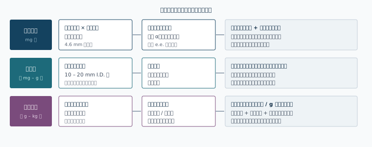
The key is that the "stationary phase selection conclusion" produced by the first layer can be reused directly in the second and third, without breaking down because the media are unobtainable.
6.3Economics of self-packed preparative columns
The solution page notes that chiral stationary phases carry a high unit cost, so loading and solvent consumption at the preparative stage weigh heavily on total cost; unit production cost can be reduced by raising the injection concentration, optimising the gradient and recovering solvent, and by self-packing preparative columns on a packing station rather than buying finished columns.
Broken down into a calculable cost structure:
| Cost item | Determining factors | Means of control | Room for control (our inference) |
|---|---|---|---|
| Depreciation of the chiral media | Media unit price ÷ (mass packed × cumulative throughput over column lifetime) | Self-packing lowers unit media cost; extend column life (guard column, sample filtration, avoiding incompatible solvents) | A large effect — finished and self-packed columns usually differ appreciably in unit media cost |
| Net solvent consumption | Specific consumption = solvent volume ÷ product mass | Raise injection concentration and loading; use polar organic mode to shorten the cycle; recover solvent by distillation and reuse | Recovery is usually in the 70%–90% range, depending on the solvent system |
| Equipment and labour | Cycle time × number of batches | Stacked injections, automated peak cutting, continuous chromatography | Determined jointly by cycle time and loading; the scope for improvement depends on how far the method is optimised |
| Yield loss | The trade-off in the cutting window | Recover the minor enantiomer, racemise it chemically and return it upstream | Can raise the 50% theoretical ceiling to close to quantitative (provided the racemisation conditions are feasible) |
The precondition for raising the injection concentration
Raising the injection concentration is limited by sample solubility in the mobile phase. On this point, a stationary phase usable with strong solvents such as dichloromethane, chloroform and THF (section 5.3) has a direct advantage: a concentrated sample solution can be made up in a strong solvent and carried on a weakly eluting mobile phase, raising the amount injected per run without noticeably affecting peak shape. If the stationary phase does not tolerate these solvents, the injection concentration is locked to the solubility ceiling.
6.4The division of roles with COSMOSIL CHiRAL
| Stage | COSMOSIL CHiRAL | ChiralONE |
|---|---|---|
| Method development and initial screening | Three immobilised selectors (A / B / C) in 3 µm analytical columns, covering the two orthogonal dimensions of backbone and electronic effect; strong solvents widen the screening space | Polysaccharide derivative selectors adding a further screening dimension across normal phase / reversed phase / polar organic modes |
| Method validation and release analysis | 3 µm, 4.6 × 250 mm gives resolution margin; the application conditions are published and easy to check, which helps method transfer | Usable as an orthogonal confirmatory column |
| Semi-preparative (hundreds of mg – g) | 5 µm finished columns in 10 mm and 20 mm I.D. | Self-packed columns of 10 – 30 mm I.D. |
| Preparative scale-up (hundreds of g – kg) | — | Bulk media plus packing station and packing service, self-packed to the target column diameter |
| paired with | Published application data and conditions | A DL amino acid kit (for the indirect approach and amino acid chiral purity), method development support, and a preparative column packing service |
The two are not alternatives. The more common combination is to complete analytical screening and establish the e.e. method on the three immobilised COSMOSIL CHiRAL selectors, then, once the selector type and elution mode are settled, scale up at the preparative stage with ChiralONE media self-packed in the same mode, while retaining the analytical method for process control and release.
This part gives a directly executable screening and optimisation workflow, together with the key points of e.e. method validation and how to handle common problems.
7.1Designing the screening matrix
The hit rate data in section 5.5 show that the probability of success with a single column under a single condition is limited, so screening should be organised as a matrix. One executable three-tier screening scheme is as follows.
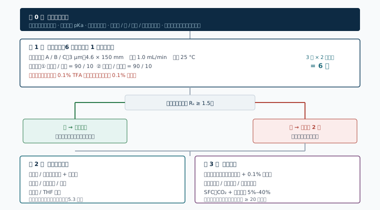
Tier 1 covers most samples with a small number of conditions; tiers 2 and 3 address the samples tier 1 missed, expanding along the solvent and mode dimensions respectively.
7.2Mobile phase systems and additives
| Component | Usual range | Function | Points to note |
|---|---|---|---|
| Alkane (hexane / heptane) | 50%–98% | The bulk solvent in normal phase, providing a weakly eluting background | Heptane is less toxic and can replace hexane; its viscosity is slightly higher, so backpressure rises accordingly |
| Alcohol modifier (ethanol / isopropanol / methanol) | 2%–50% | Adjusts eluting strength; takes part in chiral recognition and changes α | Changing the type takes priority over adjusting its proportion; isopropanol is more viscous |
| Acidic additive (TFA / formic acid / acetic acid) | 0.1% | Suppresses dissociation of an acidic solute and its interaction with silanols, improving tailing | TFA causes ion suppression in MS; use formic acid for MS work |
| Basic additive (diethylamine / triethylamine) | 0.1% | Suppresses ionic interaction between a basic solute and residual silanols | The column must be equilibrated thoroughly after changing additive; dedicating a column to acid or to base use is advisable |
| Reversed phase buffer salt (phosphate / ammonium formate / ammonium acetate) | 5–20 mmol/L | Controls pH and ionic strength | pH must stay within the tolerance of the stationary phase (pH 2–9 for COSMOSIL CHiRAL); a salt-containing mobile phase cannot be switched directly to normal phase solvents |
Transition steps when switching mode
Normal and reversed phase cannot be switched directly. The suggested transition sequence is: normal phase system → isopropanol (neat) → ethanol or methanol (neat) → the target reversed phase system; the reverse order applies for the opposite switch. When leaving a salt-containing system, flush first with salt-free water/organic, then move to neat organic, to avoid salt precipitating in the column or the tubing. At least 20 column volumes are advisable for each transition step.
7.3The order in which to work the optimisation variables
- Type of modifier— the largest effect on α; try this first. Ethanol and isopropanol often give markedly different selectivity.
- Column temperature— lowering the temperature raises α in most systems (section 4.7). Examine the range 10–40 °C in 5 °C steps, watching for proximity to the isoelution temperature.
- Proportion of modifier— mainly affects k. The aim is to keep k between 2 and 10; below k = 1 resolution is noticeably lost, above k = 10 the time cost is not worth it.
- Type and concentration of additive— affects peak shape and, in some systems, α.
- Flow rate— affects N. At the analytical stage the flow can be dropped to 0.5 mL/min to buy resolution; at the preparative stage the opposite applies and the flow should be raised as far as the resolution margin allows.
- Column length and particle size— adjust last. Rs ∝ √N, with diminishing returns; but changing from 5 µm to 3 µm raises N without lengthening the run.
7.4Where reversed phase and polar organic modes fill the gaps
- Sample solubility in an alkane system is too low— a sample solution of sufficient concentration cannot be made up under normal phase conditions and preparative loading is limited, so switch to polar organic mode.
- MS coupling is needed— a normal phase mobile phase is incompatible with an ESI source, so reversed phase or polar organic mode (with ammonium formate/acetate) is the workable choice.
- Bioanalysis— for aqueous matrices such as plasma and tissue homogenate, reversed phase mode allows direct injection.
- α is insufficient in normal phase— switching mode itself provides new selectivity; this is tier 3 of the screen in section 7.1.
7.5Indirect approach: chiral derivatization

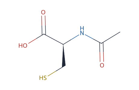
Two commonly used pre-column derivatization reagents. Derivatization converts enantiomers into diastereomers, and the separation is carried out on an ordinary C18 column.
A chiral derivatizing reagent (CDR) is reacted with the enantiomers to give a pair of Diastereomers, whose physicochemical properties differ and which can be separated on an ordinary C18 column (see Fig. 1-2).
| Dimension | Indirect (chiral derivatization) | Direct (chiral stationary phase) |
|---|---|---|
| Columns | Ordinary C18, low cost | A chiral column, higher unit cost |
| Samples it suits | Must contain a reactive group (amino, carboxyl, hydroxyl); suits amino acids well | Essentially unrestricted by functional group |
| Sample preparation | Requires a derivatization reaction, adding steps and time | Direct injection |
| Main risks | The optical purity of the derivatizing reagent itself, differing reaction rates for the two enantiomers (a kinetic resolution effect), side reactions and racemisation | Method robustness is fairly sensitive to conditions |
| Suitability for preparative work | The derivatising group must be removed from the product, adding process steps | The product can be used directly |
| Validation requirements | Derivatization yield, reagent optical purity and reaction reproducibility must be examined additionally | Carried out as ordinary method validation |
The position taken on the solution page is that the direct approach applies more broadly, while the indirect approach retains a cost advantage for amino acid compounds. Chiral purity determination for amino acids can be established as a pre-column derivatization method with the DL amino acid kit.
7.6Key points of method validation for e.e. determination
An e.e. method is essentially about quantifying a trace of the minor enantiomer in the presence of a large excess of the major. That positioning makes the focus of validation different from an ordinary assay method.
| Validation element | Point | FAQ |
|---|---|---|
| Specificity / resolution | Rs ≥ 1.5 for the two enantiomers; confirm in the actual drug substance or drug product matrix that no interfering peak co-elutes | An excipient or degradation product falling at the retention position of the minor enantiomer |
| elution order | The minor enantiomer should elute before the main peak | If the minor peak comes after the main peak it sits on the main peak's tail and the integration error is greatly magnified |
| LOD / LOQ | LOQ should be below half the limit; on a 0.1% limit, LOQ must be ≤ 0.05% | Insufficient injection; the minor peak lost in baseline noise |
| Linearity | Covering LOQ to 120%–150% of the limit | The range set from the main component concentration rather than the impurity concentration, leaving the low end uncovered |
| Accuracy | Examined with a reference standard of known e.e. or by spiked recovery | No reference standard for the minor enantiomer; one can be made up from the racemate and the single enantiomer |
| Robustness | Column temperature ±5 °C, modifier proportion ±10% relative, additive concentration, flow rate, different column batches | Column temperature not examined, so results drift in a system close to the isoelution temperature (section 4.7) |
| Solution stability | Examine whether the sample racemises in the solvent | A stereocentre bearing an active hydrogen racemises slowly in a basic solvent, so e.e. falls with standing time |
On adjusting the elution order
If the minor enantiomer elutes after the main peak, try changing the selector (a column with a different backbone or substituent often gives the opposite elution order), or move the column temperature to the other side of the isoelution temperature. If neither is possible, reduce tailing interference by lowering the amount of main component injected and raising detection sensitivity, and specify the integration parameters explicitly in the method.
7.7Common problems and troubleshooting
| Symptom | Possible cause | Direction to take |
|---|---|---|
| The two peaks do not separate (α ≈ 1) | Selector mismatch; unsuitable modifier type; column temperature too high | Change column and modifier as in 7.1; lower the column temperature; move to tier 2 and 3 screening |
| Severe Peak Tailing | Interaction of an acidic or basic solute with residual silanols; sample overload | Add 0.1% of the corresponding additive; reduce the injection to confirm whether it is overload |
| A raised plateau appears between the two peaks | On-column interconversion (an atropisomer or an easily racemised stereocentre) | Lower the column temperature; shorten the retention time; state the configurational stability of the compound in the methodology |
| Retention time drifts from day to day | Trace water varying in a normal phase system; column temperature uncontrolled; backpressure too low with a pure alkane, making pump delivery unstable | Control the water content of the mobile phase or add a fixed proportion of alcohol; use a column oven; move to a 3 µm column to raise backpressure |
| A sudden fall in efficiency | Column head fouling; an incompatible solvent used; bed disturbance | Backflush or flush with a strong solvent (THF and dichloromethane are usable on immobilised types); check solvent compatibility; fit a guard column |
| e.e. results vary between batches | Column temperature fluctuating near the isoelution temperature; inconsistent integration parameters; racemisation in the sample solution | Fix the column temperature and include it in robustness; standardise the integration method; examine solution stability and specify a use-by time after preparation |
| Efficiency does not recover after a mode change | Insufficient transition flushing; salt precipitated in the column | Re-equilibrate following the transition sequence in 7.2; wash the salt out of a salt-containing system with water/organic first |
An analytical method aims at resolution; a preparative method aims at throughput per unit time and unit cost. This part gives the conversion from analytical to industrial column and the engineering constraints involved.
8.1Loading, overload and the touching-band mode
Preparative chromatography runs in the non-linear region— once the amount injected is large enough the adsorption isotherm is no longer a straight line, and the peak changes from a symmetrical Gaussian to a right triangle. This is the main difference in principle between preparative and analytical work.
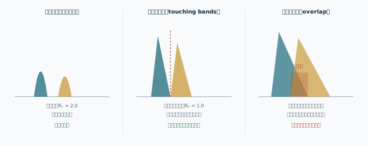
The aim of preparative method development is to establish the "touching-band injection amount" and the acceptable overload range above it, not to maintain analytical-grade resolution.
Resolution margin at the analytical scale determines preparative throughput
How much overload can be tolerated at the preparative stage depends on the α and Rs margin under analytical conditions. If Rs = 1.5 analytically, there is very little overload room in preparative work; if Rs = 3.0, the amount injected per run can be raised substantially while product purity is maintained. Spending more time raising α during method development therefore pays back at the preparative stage in the form of throughput. This is the practical reason section 4.8 stresses addressing α first.
Two kinds of overload must be distinguished:
- Concentration overload— high sample concentration, small injection volume. The peak becomes a right triangle and the retention time moves earlier. This is the form commonly used in preparative work.
- Volume overload— low sample concentration, large injection volume. The peak broadens into a rectangle. It is forced on you when sample solubility in the mobile phase is limited, and throughput is lower than with concentration overload.
Raising sample solubility is therefore a direct way of raising preparative throughput. A stationary phase that allows a strong dissolving solvent (sections 5.3 and 6.3) has a real advantage here.
8.2Scale-up calculations from analytical to preparative column
Keeping the same particle size, column length and linear velocity, scale by the ratio of column cross-sectional areas:
| Parameter | Conversion | Notes |
|---|---|---|
| Flow rate | F₂ = F₁ × (d₂ / d₁)² | d is the column internal diameter. Keeping the linear velocity constant keeps efficiency and retention time constant with it |
| Injection volume | m₂ = m₁ × (d₂ / d₁)² × (L₂ / L₁) | The second term is 1 when the column length is the same |
| Injection volume | V₂ = V₁ × (d₂ / d₁)² | As above |
| retention time | Unchanged | On the premise that column length and linear velocity are unchanged |
| Column volume | Vcol = π (d/2)² L | Used to calculate the solvent needed for equilibration and flushing |
| Column ID | Cross-sectional area ratio | Flow rate | Relative injection amount | Role |
|---|---|---|---|---|
| 4.6 mm | 1.0 | 1.0 mL/min | 1 × | Analytical / reference |
| 10 mm | 4.7 | 4.7 mL/min | 4.7 × | Semi-preparative |
| 20 mm | 18.9 | 18.9 mL/min | 18.9 × | Preparative |
| 30 mm | 42.5 | 42.5 mL/min | 42.5 × | Gram-scale preparative |
| 50 mm | 118 | 118 mL/min | 118 × | Ten-gram scale |
| 100 mm | 473 | 473 mL/min | 473 × | Hundred-gram scale / pilot |
| 200 mm | 1890 | 1.89 L/min | 1890 × | Kilogram scale / production |
Three points where scale-up departs from prediction
- Extra-column volume— the tubing and detector cell volume of an analytical system are not negligible relative to the column volume, whereas on a preparative system they are. Peak shape after scale-up is often better than a linear prediction.
- packing uniformity— bed uniformity is poorer in a large-diameter column than a small one, so the efficiency achieved is lower than that of the analytical column. This is where dynamic axial compression (DAC) has its value (section 8.3).
- Thermal effects— frictional heating and radial temperature gradients in a large-diameter column produce extra peak broadening, more noticeably at high flow rates.
8.3Packing technique and bed stability
The performance of a preparative column is largely determined by packing quality. The usual approaches along the scale ladder:
| Column diameter range | Usual packing method | Means of stabilising the bed | What matters |
|---|---|---|---|
| 4.6 – 30 mm | Slurry packing (high pressure) | Column head compression | Choice of slurry solvent, packing pressure and hold time |
| 30 – 100 mm | Slurry packing or a semi-automatic packing station | Column head compression or axial compression | Packing reproducibility; a void at the column head from bed settling |
| 100 – 600 mm | Dynamic axial compression (DAC) | The piston applies axial pressure continuously and the bed is always under compression | Condition of the piston seal and frit, compression pressure setting, bed height consistency |
The value of DAC is that the bed is under compression throughout use, voids from settling are compensated automatically by the piston, so efficiency is maintained over long operation and the media can be discharged, cleaned and repacked at the end of column life. For chiral media with their high unit cost, this bears directly on the effective depreciation period of the media.
Packing points specific to chiral media
The selector layer of a polysaccharide chiral medium is attached to the silica surface, so the slurry solvent used in packing must be compatible with the stationary phase. Immobilised types allow a wide choice of slurry solvent; coated types must avoid solvents that dissolve the selector (compare Table 5-2). Excessive packing pressure can fracture the particles, so the pressure rating of the medium must be observed.
8.4Continuous chromatography: SMB and MCSGP
The inherent inefficiency of batch chromatography is that for most of the time only a short section of the column is actually separating, while the rest is occupied by washing and equilibration. Continuous chromatography improves on this with columns in series and valve switching.
| Mode | Principle | When to Use This Service | Constraints |
|---|---|---|---|
| Batch (single column) | Injection, collection and equilibration in sequence | Development stage, frequent product changeover, small batches | High specific solvent consumption; low stationary phase utilisation |
| Stacked injection / peak shaving recycle | The overlapping middle fraction is returned to the head of the column and separated again | Small α, insufficient single-pass resolution | The system must support valve switching; the peak broadens with each cycle |
| SMB(simulated moving bed) | Columns in series, with feed and draw ports switched periodically to simulate countercurrent movement of the stationary phase | binary separation, and chiral resolution is its classic application | Applies only to two-component separations; process development is complex; changeover cost between products is high |
| MCSGP (multi-column countercurrent gradient purification) | Achieves continuous countercurrent operation under gradient elution, with internal recycling of the intermediate fraction | Separations of three or more components where the target sits in the middle | Higher equipment and control complexity |
SMB fits chiral resolution well because chiral resolution is fundamentally a binary separation— only two enantiomers have to be separated, which is exactly the premise SMB requires. In published reports, the specific solvent consumption and stationary phase requirement of SMB in tonne-scale production of a chiral API are usually markedly lower than for batch chromatography (a qualitative conclusion inferred here; the actual figures depend on the system).
8.5Preparative SFC
Preparative chromatography with supercritical CO₂ as the bulk mobile phase suits chiral separation for three reasons:
- Low mobile phase viscosity— it can be run at high linear velocity with controllable backpressure, giving higher throughput per unit time than normal phase HPLC; in the example in section 5.6 the SFC flow rate is three times that of HPLC.
- Simple work-up— CO₂ vaporises on depressurisation, leaving only a small amount of alcohol modifier in the fraction, so the evaporation load is low.
- Lower organic solvent usage— this cuts solvent purchase and waste treatment costs directly, with a clear improvement in PMI.
The constraints are the capital cost and the maintenance requirements of a pressure system, and sample solubility in the CO₂/alcohol system. COSMOSIL CHiRAL columns can be used in SFC and, according to the published literature, their separation performance is comparable to HPLC (section 5.6), so a method developed on HPLC can be transferred fairly quickly to an SFC platform for evaluation.
8.6Solvent recovery and unit production cost
The specific solvent consumption of chiral preparative work (L solvent / kg product) is usually higher than for ordinary reversed phase preparative work, because α is small in a chiral separation and the loading per run is limited. Solvent recovery therefore carries greater weight in the cost structure.
| Mode | Main solvents | Recovery method | Characteristics |
|---|---|---|---|
| Normal phase | Hexane/heptane + alcohol | Fractional distillation, recombined to composition | The boiling points differ appreciably, so recovery is relatively easy; water content and variation in the alcohol proportion of the recovered liquid must be controlled |
| Polar organic | Acetonitrile / methanol | Recovery by distillation | A single-solvent system, so recovered composition is easy to control; energy use in concentrating the product is low |
| Reversed phase | Water + acetonitrile/methanol | The organic phase is recovered by distillation; the aqueous phase is discharged or treated | The energy and cycle time of dewatering the product (lyophilisation or extraction) are the main burden |
| SFC | CO₂ + alcohol | CO₂ recycled, alcohol recovered by condensation | The lowest net solvent consumption; higher capital cost |
A usable formula for costing:
Unit production cost = media depreciation/kg + net solvent consumption × solvent unit price + energy and labour/kg + yield loss converted to cost
where net solvent consumption = total solvent used × (1 − recovery). Raising recovery from 70% to 90% cuts net solvent consumption to one third, and the weight of this item in total cost falls noticeably.
8.7Column life and regeneration
- Prevention first— filter samples through 0.22 µm before injection; fit a guard column packed with the same medium as the main column; avoid mobile phases outside pH 2–9; avoid incompatible solvents (coated types especially).
- Routine regeneration— flush with a strongly eluting solvent (isopropanol or THF in a normal phase system; dichloromethane or chloroform on an immobilised type) for 20–30 column volumes, then return to the working mobile phase and equilibrate.
- Column head treatment— where a void at the column head causes split peaks, the head of a preparative column can be removed and media added; a DAC column compensates automatically by adjusting the piston compression.
- Deciding on end of life— judge on the resolution and plate count in the system suitability test, set a percentage fall from the initial value as the retirement threshold, and record it in the equipment log.
This part is a quick reference that can be used on its own, separately from the main text.
9.1Quick reference for mode and column selection
| Sample characteristics | Suggested starting mode | Suggested starting mobile phase | Notes |
|---|---|---|---|
| Neutral, low to medium polarity, soluble in alkanes | Normal phase | Hexane / ethanol = 90/10 Hexane / isopropanol = 90/10 | Usually the highest hit rate; try this first |
| Contains an acidic group such as carboxyl | Normal phase | The above with 0.1% TFA or formic acid | Without acid it tails easily and detection suffers |
| Contains a basic group such as an amine | Normal phase or polar organic | The above with 0.1% diethylamine | Basic compounds often show better peak shape in polar organic mode |
| Low solubility in alkanes | Polar organic | Neat acetonitrile or neat methanol with 0.1% additive | Can raise preparative loading markedly |
| Highly polar, water soluble, salt form | Reversed phase | Acetonitrile / water, or methanol / buffer salt | pH must stay within 2–9 |
| MS coupling needed | Reversed phase or polar organic | A 5–10 mmol/L ammonium formate / ammonium acetate system | Avoid TFA and diethylamine |
| Biological samples (plasma, tissue) | Reversed phase | Buffer / acetonitrile gradient | Protein must be removed in sample preparation |
| Preparative scale-up, optimising throughput | SFC or polar organic | CO₂ + 10%–30% alcohol; or neat acetonitrile | Low solvent recovery load |
| The sample must be dissolved in a strong solvent | Normal phase (immobilised column) | Dissolve in dichloromethane or THF, with a normal phase system as the carrier | Requires an immobilised stationary phase; coated types are unsuitable |
| Problem encountered | First choice | Second choice |
|---|---|---|
| α < 1.05, the two peaks almost coincide | Change the selector (different backbone or different substituent) | Change the type of modifier; lower the column temperature to 10–15 °C |
| α is adequate but Rs < 1.5 | Change from 5 µm to 3 µm; change column length from 150 mm to 250 mm | Lower the flow rate; lower the modifier proportion to raise k |
| Retention too strong (k > 15) | Raise the modifier proportion | Change to a more strongly eluting modifier |
| Retention too weak (k < 1) | Lower the modifier proportion to 2%–5% | Change to a more weakly eluting modifier |
| The minor enantiomer comes after the main peak | Change the selector to reverse the elution order | Move the column temperature to the other side of the isoelution temperature; reduce the loading of the main peak |
| Preparative loading is insufficient | Raise sample solubility (use a strong dissolving solvent or switch mode) | Raise the analytical Rs margin to widen the overload room |
9.2Chinese–English glossary
| Chinese | English | Notes |
|---|---|---|
| Chiral | chirality | The property of not being superimposable on one's mirror image |
| Enantiomers | enantiomer | A pair of stereoisomers that are mirror images and not superimposable |
| Diastereomers | diastereomer | Stereoisomers that are not mirror images |
| Racemate | racemate | An equal mixture of the two enantiomers |
| Meso compound | meso compound | Contains stereocentres but is achiral overall |
| Atropisomer | atropisomer | An axially chiral isomer arising from hindered rotation |
| Eutomer / distomer | eutomer / distomer | The more / less active enantiomer |
| Enantiomeric excess | enantiomeric excess (e.e.) | The principal measure of chiral purity |
| Chiral stationary phase | chiral stationary phase (CSP) | The stationary phase used in a direct separation |
| Chiral selector | chiral selector | The structural unit on the stationary phase responsible for chiral recognition |
| Coated / immobilised type | coated / immobilized | How the selector is attached to the support |
| Chiral derivatizing reagent | chiral derivatizing reagent (CDR) | The reagent used in the indirect approach |
| Normal phase / reversed phase / polar organic mode | normal phase / reversed phase / polar organic mode | The three liquid chromatography elution modes |
| Supercritical fluid chromatography | supercritical fluid chromatography (SFC) | Supercritical CO₂ as the bulk mobile phase |
| Selectivity factor | selectivity factor (α) | α = k₂ / k₁ |
| Resolution | resolution (Rs) | The measure of how far two peaks are separated |
| Kinetic resolution / dynamic kinetic resolution | kinetic resolution / dynamic kinetic resolution | Resolution based on a difference in reaction rate |
| Chiral switch | chiral switch | The product development strategy of moving from a racemate to a single enantiomer |
| Simulated moving bed | simulated moving bed (SMB) | A continuous chromatography technique suited to binary separation |
| Dynamic axial compression | dynamic axial compression (DAC) | The bed compression technique used in large-diameter preparative columns |
| isoelution temperature | isoelution temperature | The temperature at which α = 1; crossing it reverses the elution order |
9.3Sources
- COSMOSIL CHiRAL Series product page (technical parameters, solvent tolerance data, hit rate trial, SFC conditions, application conditions, formats) — NACALAI TESQUE, INC.:https://www.nacalai.com/global/cosmosil/index/CHiRAL.html
- COSMOSIL CHiRAL Series product handbook (PDF) — NACALAI TESQUE, INC.:https://www.nacalai.com/global/download/pdf/COSMOSIL_CHiRAL_Series.pdf
- Chiral Drug Separation · Chromatography Solutions (ChiralONE positioning, the three modes, the indirect approach, e.e. determination, preparative work and scale-up) — Microwants:https://www.microwants.com/solution-chiral.html
- ICH Q6A, Q3A(R2), Q3B(R2), Q2(R2) guidelines
- FDA, Policy Statement for the Development of New Stereoisomeric Drugs (1992)
- Easson L.H., Stedman E., Biochem J., 1933 (the original proposal of the three-point interaction model)
Notes on use
Content marked "our inference" in this document has no published statistical source and serves only as experience-based reference; it should not be cited directly as a technical basis. Product specifications, availability and specific parameters are governed by the manufacturer's latest literature and by confirmation on enquiry. The example method conditions come from published application literature and illustrate how conditions are designed; an actual project must redevelop and validate against its own sample.
Applying the panorama to your compound
Send us the structure, the target e.e., the quantity required and the development stage, and we will come back with screening conditions and a suggested scale-up route